E07 — 36-slot / 28-bar 4-pole squirrel-cage induction machine
IM · Rectangular Tooth · 36 slots / 4 poles · 4.673 N·m at 1418 rpm · 67.1 % efficient · 5717 nodes · 109 s
What you need to run it: the Python API and the Machines module. Opening the model and reading results that are already there never requires a licence. The Thermal module is needed only for the --thermal run. The machine itself does not need it.
At a glance
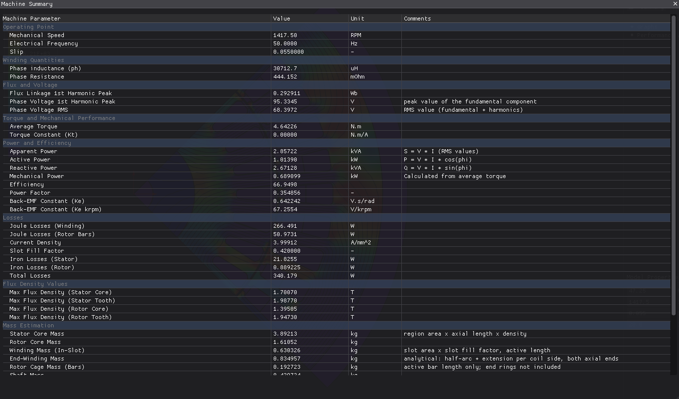
| Quantity | Value | Unit |
|---|---|---|
| Speed | 1418 | rpm |
| Electrical frequency | 50.0 | Hz |
| Slip | 0.055 | — |
| Average torque | 4.673 | N·m |
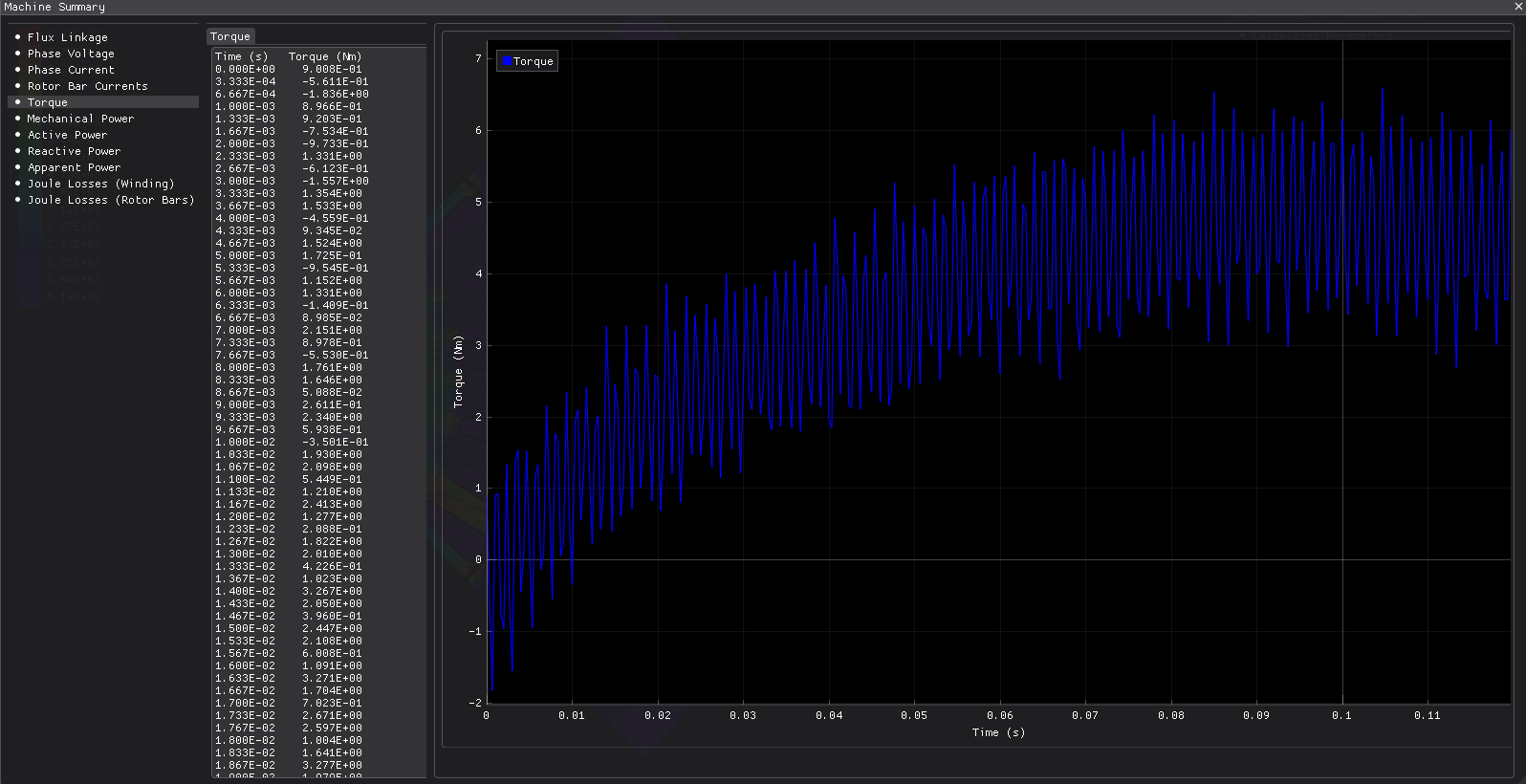
| Torque ripple | 79.8 | % |
| Mechanical power | 0.694 | kW |
| Efficiency | 67.08 | % |
| Power factor | 0.355 | — |
| Total losses | 340.4 | W |
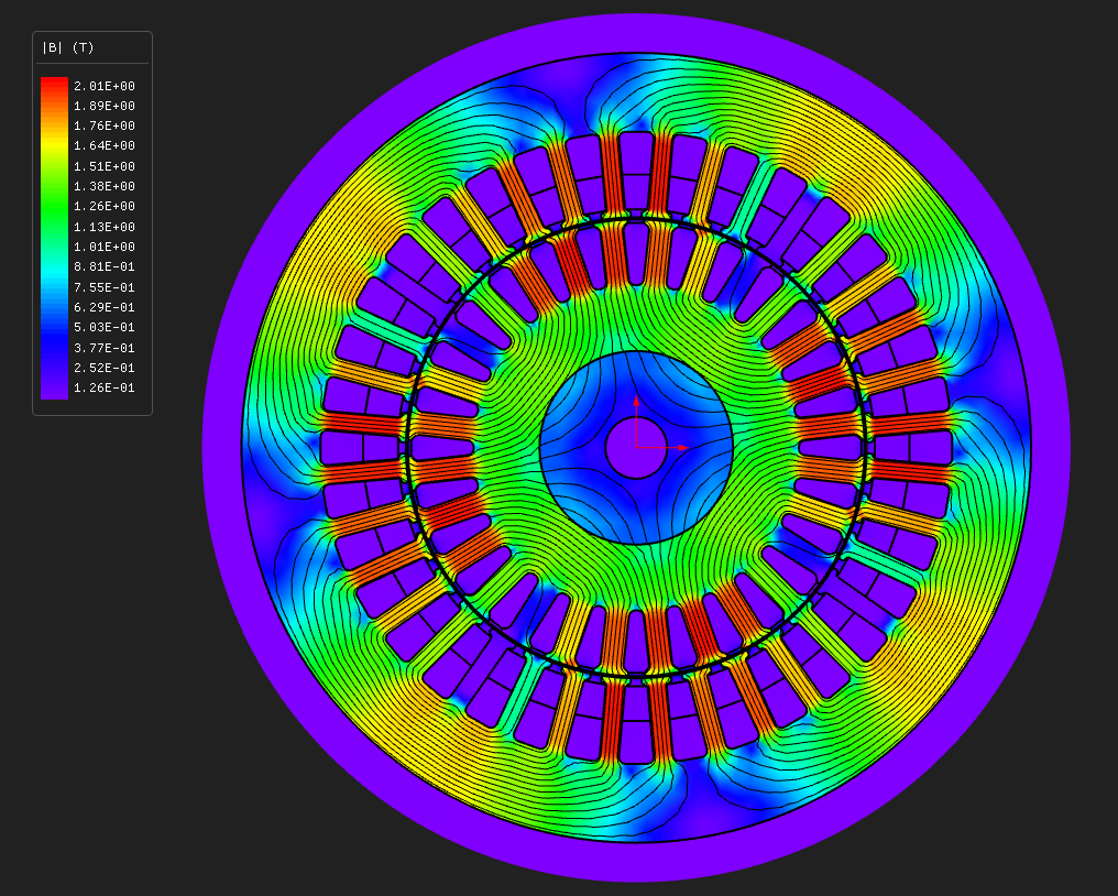
| Max B, stator tooth | 1.997 | T |
| Mesh | 5717 nodes, 10529 elements, P1 | — |
| Wall time, end to end | 109 | s |
The first induction machine to open, and the first model here whose rotor current is solved rather than imposed. The cage's bar currents are unknowns of the solve, held closed by the circuit solver, and the example walks the whole electrical loop: geometry, cage circuit, equivalent-circuit extraction, then the torque, current, power-factor and efficiency curves against slip and speed.
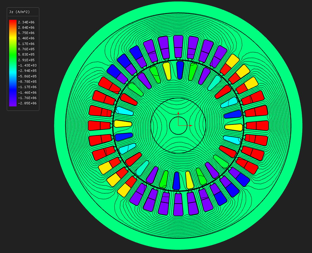
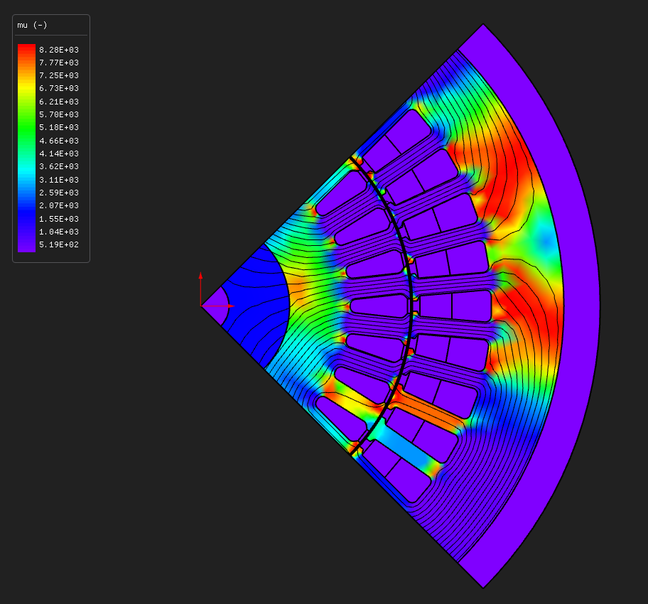
A quarter of the machine is solved — nine slots and seven bars over 90°, closed anti-periodically.
The design
| Layer | Radii (mm) | Set by |
|---|---|---|
| shaft bore | 4.700 | derived from rotor shaftThickness 10 |
| rotor shaft | 4.7 → 14.7 | shaftThickness 10 |
| rotor yoke | 14.7 → 24.7 | coreThickness 10 |
| rotor bars | 24.7 → 34.7 | slotDepth 10, slotWidth 4.0, 28 bars |
| air gap | 34.7 → 35.0 | airGap 0.3 |
| stator bore | 35.000 | ID 70 |
| slot bottom | 48.000 | slotDepth 13, slotWidth 3.4, 36 slots |
| stator OD | 60.000 | OD 120, back iron 12 |
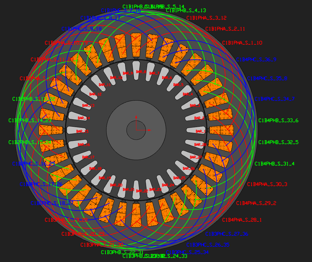
Rectangular teeth on both sides, 90 mm axial length, two pole pairs, and a 1 kW industrial frame in round terms.
Thirty-six against twenty-eight is a deliberate pairing. The two counts share only a factor of four, which keeps the slot-harmonic torques from lining up, and it still leaves a usable symmetry sector.
How much of an induction machine you have to solve
The sector is the greatest common divisor of coils per phase, poles and rotor bars — and coils per phase depends on the layer count, because a double layer puts one coil in every slot where a single layer puts one in every second slot.
This machine has twelve coils per phase as a double layer, so gcd(12, 4, 28) = 4 and you solve 90°. Built as a single layer it would have six, gcd(6, 4, 28) = 2, and you would solve 180° — four times the mesh for the same machine. Worth checking before you commit to a winding.
Both slot mouths are deliberately wide, half the stator slot width and 0.6 of the rotor's. A narrow mouth is a leakage path, and the first version of this design had a nearly closed rotor slot in the die-cast style. Its extracted leakage factor came out at 0.34, about five times a healthy machine's, and that is exactly why its power factor was 0.24. Opening both mouths and moving the rated slip onto a third of the extracted breakdown slip is the whole difference between that machine and this one.
Winding and materials
| Stator core and rotor yoke | M-19 Steel, nonlinear BH |
| Rotor shaft | 1020_steel |
| Rotor bars | conductivity 2.4 × 10⁷ S/m written on the region — die-cast aluminium at about 100 °C |
| Winding | three-phase distributed double layer, q = 3, full pitch |
| Turns per coil | 30 |
| Slot fill | 0.42 |
| Parallel branches | 4 |
| End winding | 20 mm extension |
The shipped material library carries magnetic materials only, so bar conductivity goes straight onto the region rather than coming from a material.
Iron loss is fitted from a specific-loss table the script generates, representative of a 0.5 mm non-oriented grade at about 3.3 W/kg for 50 Hz and 1.5 T — the class of steel a small industrial motor is actually built from.
Operating point
| Excitation | 20 A peak, slip 0.055, shaft speed 1417.5 rpm |
| Supply | 50 Hz, so 1500 rpm synchronous |
| Circuit solver | on — the cage is closed |
| Eddy currents in the bars | off, see below |
| Equivalent-circuit extraction | on, time-harmonic method |
| Window solved | six electrical periods, 60 steps each |
Eddy currents in the bars are off on purpose. At 5.5 % slip the rotor sees 2.75 Hz, and the skin depth in aluminium at that frequency is about 35 mm against a 10 mm bar. There is nothing for the skin effect to do, and the circuit resistance already carries the physics. E08 is the machine where that stops being true.
Six periods, because the rotor takes time to settle. The rotor flux time constant here is around 40 ms, which is two electrical periods. Solve a shorter window and you are reading the energisation transient rather than the answer. This is the main difference in feel between simulating an induction machine and simulating a PM machine, and it is why this model takes a couple of minutes where the PM examples take one.
Running it
Open im_36s28r_rect_tooth.nbl and press Solve. The solved field is not shipped with this
model — six periods at 60 steps on a cage machine is a 167 MB file — so for an induction
machine, "open it and look" means opening the model and pressing solve. Budget about four
minutes for the whole thing, including the extraction stages and the curves.
From Python:
python build_im_36s28r_rect_tooth.py                  # build, solve, analyse, report
python build_im_36s28r_rect_tooth.py --no-solve       # geometry and mesh only
python build_im_36s28r_rect_tooth.py --no-performance # skip the slip and speed sweeps
python build_im_36s28r_rect_tooth.py --thermal        # plus the thermal handoff
What to look at
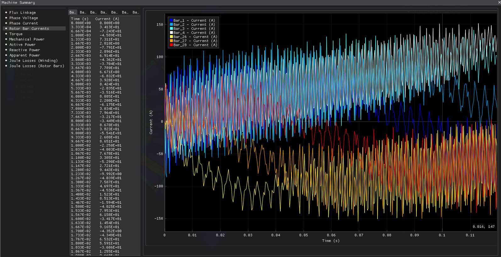
The cage really is closed. Switch the circuit solver off and the cage becomes an open
circuit: no bar current, no induction, and a machine that still converges neatly into a rather
poor reluctance motor. The bar currents are in rotor_bar_current.csv, and they should vary
smoothly around the sector, peaking where the travelling field is steepest.
The extracted equivalent circuit. Two extra stages run beside the main solve: a no-load stage at line frequency, and a locked-rotor stage at a quarter of line frequency. From those you get the T-circuit — stator and rotor resistance, the two leakage inductances and the magnetising inductance — and the leakage factor that summarises them. This is the bridge between a field model and the circuit model a drive engineer works in, and it is worth comparing against the machine's own no-load and locked-rotor tests if you have them.
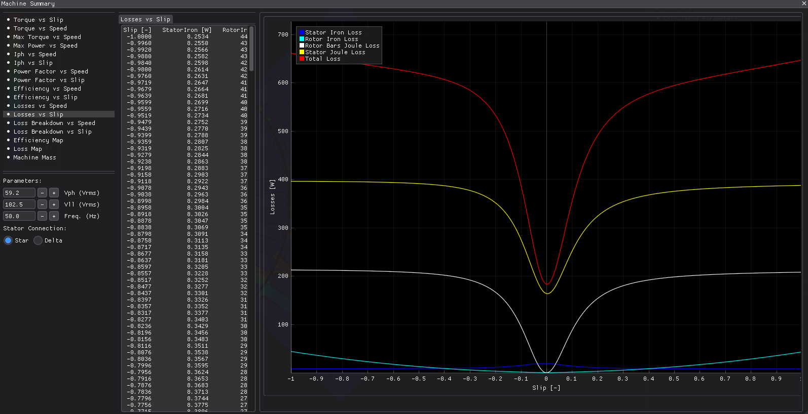
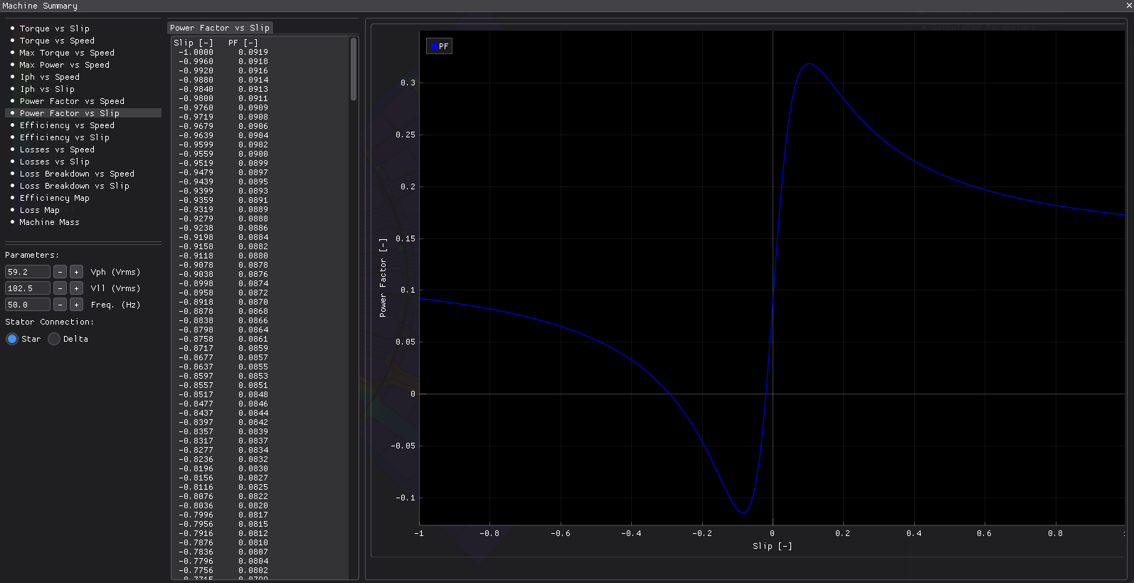
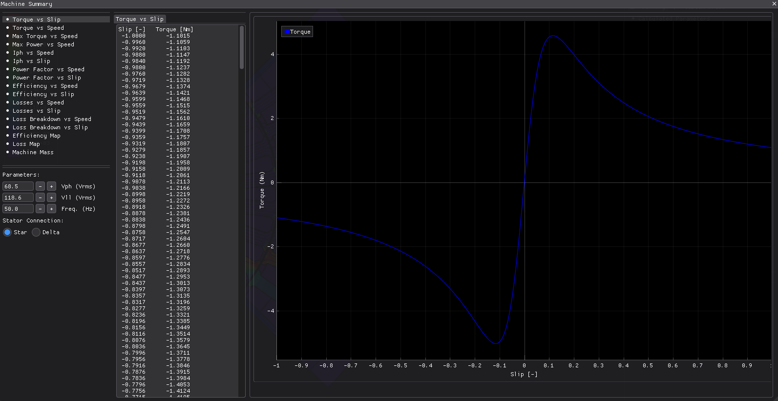
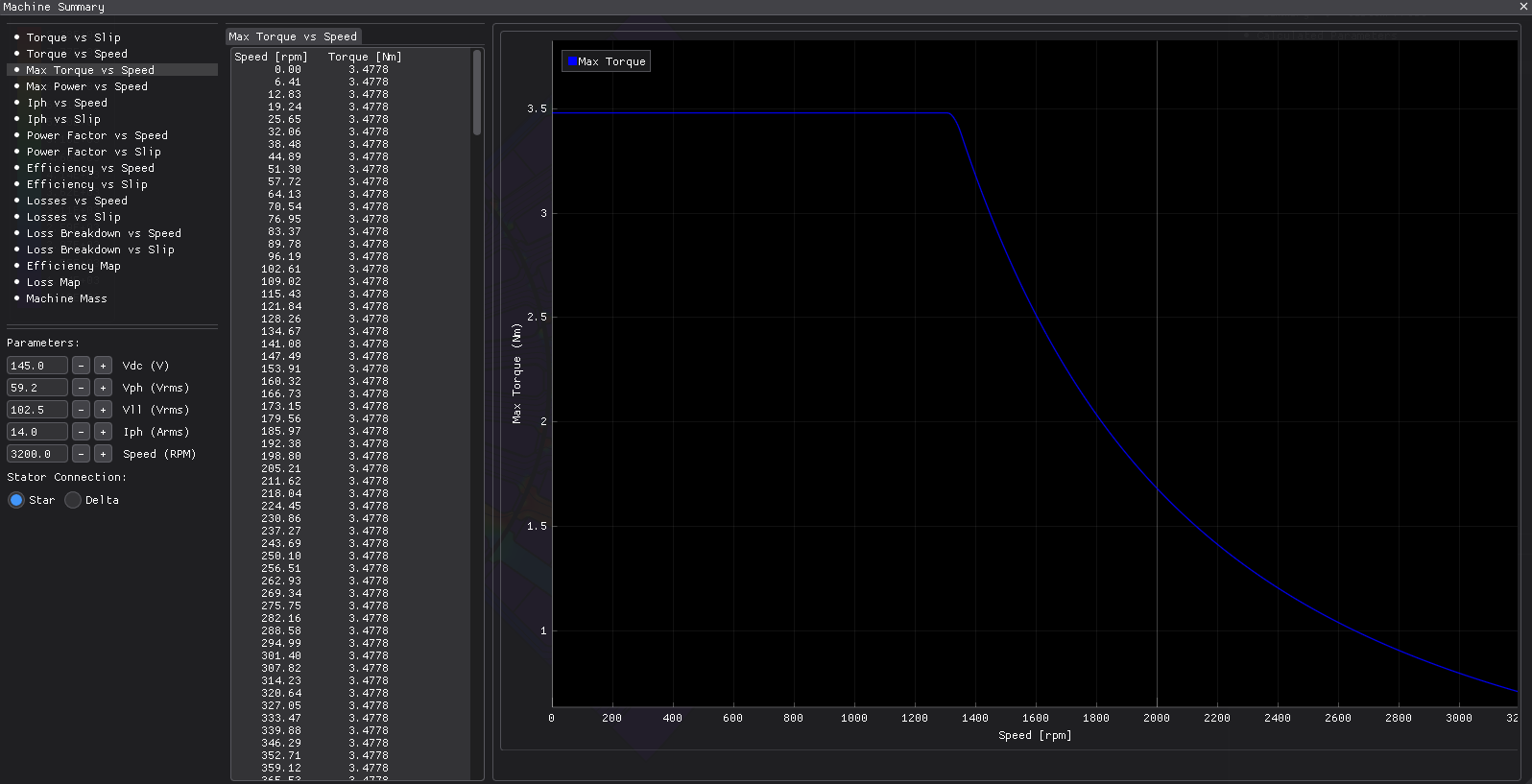
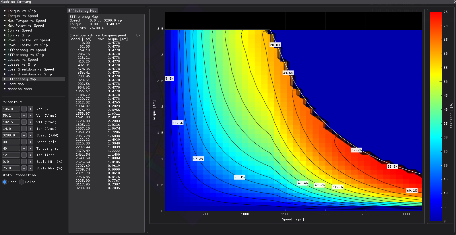
The curves. Torque, current, power factor and efficiency against slip and speed, plus an
efficiency map and a loss map, are all built analytically on the extracted circuit and driven
at a terminal voltage. They are in results/ as CSV and drawn in the PDF report. Once you have
the circuit, sweeping it costs nothing, which is the practical reason for extracting it.
Losses. Stator copper dominates, the bars carry a smaller share, and iron loss is small at
50 Hz. loss_breakdown.json has the split and the report draws the pie.
If you are scripting this, ask for a machine parameter before you ask for the circuit.
The T-circuit is assembled at the end of the summary computation, because splitting the rotor
resistance out of the locked-rotor impedance needs the stator resistance from the main run.
Call getIMEquivalentCircuit() immediately after the solve and you get zeros with a "not
valid" flag, which looks exactly like a failed extraction. Touch
getMachineCalculatedParameter first and it comes back populated.
What to trust, and what not to
The 80 % torque ripple is real for this design at this operating point. 36 slots against 28 bars puts substantial slot-harmonic content in the airgap field, and there is nothing in the geometry to suppress it — no skew, no closed slots. E08 adds skew and measures what it buys.
The power factor and efficiency are genuinely low for a sub-kilowatt frame, and they are consistent with the extracted circuit rather than an artefact of the model. A 0.3 mm air gap on this diameter gives a large magnetising reactance relative to the leakage, and the rotor resistance is close to the stator's. If you want to see a better machine, that is what the suggestions below are for.
The thermal handoff
--thermal takes the four loss channels this run produced — stator copper, bar copper, stator
iron, rotor iron — and feeds them into a separate radial layer-stack thermal model, then checks
the winding hot spot against a class F limit.
Note that it is a separate model, not this mesh. The sliding band's air layer has to be a hole for the motion to work, so the machine's own mesh has no conduction path across the air gap. Building the thermal side as a classical layer stack is the practical way round that, and it is a reasonable model of a totally enclosed frame anyway.
Try this next
--no-performanceto see how much of the run time the sweeps and maps cost against the field solve alone.- Change the rotor slot mouth. Narrow it and watch the leakage factor and the power factor move together — the first version of this design is a worked example of how much a narrow mouth costs.
- Change the slip. The rated point sits near a third of the extracted breakdown slip, which is the usual place to put it. Move it towards breakdown and watch the current, the power factor and the bar losses all climb.
--thermalto turn this run's losses into a temperature profile.
About these numbers
The dimensions are invented but plausible: a four-pole 50 Hz machine of roughly 1 kW, not a copy of a published design. The validated induction machine — a published 5 kW blower motor — lives in the validation dossier, and that is where an accuracy question belongs.
More from this run