V22 — Linear machine and the linear sliding band
Tier X - Cross-code
Tier X (cross-code, against FEMM 4.2) - priority P2
Reference frozen on 2026-08-16. Nabla 0.1.0,
solver licence mode enforcing,
run in 400.2 s.
1. Problem
One flat linear machine, asked for its force pair at eight mover positions, by three different constructions and two different codes.
A slotted armature lies below; a full-coverage permanent-magnet array on a back-iron slab is the mover above. The machine is infinite in the direction of travel, so it is solved on a window: one pole pitch with anti-periodic sides, or two with periodic ones. The mover is carried across one pole pitch either by a linear sliding band - boundary-condition type 10 on the anti-periodic window and type 9 on the periodic one - or, in the control models, by being drawn where it is.
| Pole pitch | 30 mm, 3 slots per pole pitch (slot pitch 10 mm) |
| Slots | semi-closed: 6 mm body, 2 mm opening through a 1 mm lip, root at -10 mm |
| Armature | yoke -28 ... -10 mm, teeth to the tip line at y = 0, linear iron mu_r = 2000 |
| Airgap | 2.01 mm mechanical; band lines at y = 1.0 and 1.01 mm, the 10 um strip between them a HOLE |
| Mover | magnets 2.01 ... 8.01 mm, B_r = 1.2 T, mu_r = 1.05, full pole coverage; back iron to 18.01 mm |
| Far field | A = 0 at y = -48 and y = +48.01 mm |
| Winding | single layer, full pitch, 50 turns per slot, phases held at DC 30 / -15 / -15 A |
| Depth | 100 mm, planar 2D, P1, transient with no time derivative in it |
| Sweep | 8 steps of 3.75 mm at 30 mm/s, plus record 8 - the mover one whole pole pitch on |
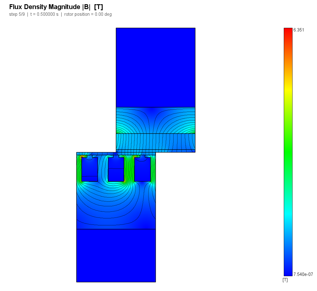
The currents are DC and nothing in the model has a time derivative - no eddy currents, no circuit, linear iron - so every record of the "transient" is a magnetostatic solve at its own mover position. The band is the only thing that changes between them, which is the point.
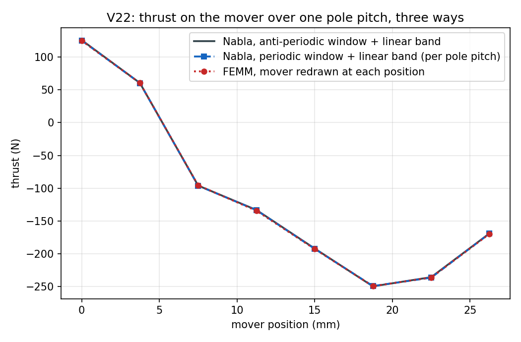
The thrust therefore traces a sinusoid across the pole pitch and passes through zero twice, with a fundamental of 160.092 N. Every force row in this case is consequently normalised by the peak of its reference series rather than pointwise: a pointwise relative error at a zero crossing is a division by nothing, and it says nothing about the rest of the sweep.
Both irons are linear on purpose. A cross-code force comparison should not also be a BH-table transcription test; that is V02's subject, and V02 records that the two codes cannot even be handed byte-identical tables (FEMM requires a curve through the origin). Here they are handed the same two numbers.
The slots are semi-closed on purpose too. An earlier draft of this machine
had fully open slots, and its detent force was as large as its useful thrust -
the regime case V05 finding F2 and V14's unjudged cogging rows say is dominated by
the instrument rather than by the solver. Narrowing the opening to below the
airgap collapsed the slot harmonic; what is left is published as
thrust_cogging_share = +16.26 % of the peak.
2. Reference
FEMM 4.2, driven by pyfemm, built by reference/femm_linear.py from the same
geometry.json that Nabla's build.py reads. FEMM has no sliding band, which is
exactly why it is the right partner for one: it is given the same machine with
the mover drawn at each of the eight offsets on a conforming mesh, one pole
pitch wide with anti-periodic sides (FEMM boundary format 5).
The force is a hand integral in both codes, on the same contour. With the
mover above the plane y = 0.5 mm - in meshed air in every model, banded,
conforming and FEMM - its outward normal is -y and the traction is
f_x = -(Bx By) / mu0                thrust
f_y = -(By^2 - Bx^2) / (2 mu0)      normal force, negative = attraction
times the model depth. That is term for term what Results.linearBandForce
computes from Bn/Bt on the mid-band contour, and it is deliberately not
either code's own stress-tensor call: two codes' normal and sign conventions are
not the thing under test, which is the lesson V02's Ampère row was written to
carry. FEMM's own mo_lineintegral(3) over the same line is recorded beside it
in femm_reference.json and reproduces the hand integral to about 0.02 % with
FEMM's opposite normal convention - the check that the hand integral is reading
the field FEMM thinks it wrote.
The eight thrust and eight normal-force values are frozen into
expected.json. extract.reference() reloads femm_reference.json every run, so
an edit to the generated file that is not matched in the frozen one is reported
as DRIFT rather than quietly becoming the new reference, and the nightly gate
needs no FEMM installation. See the case's reference notes.
The other two references are Nabla itself, and they are exact rather than
approximate. A periodic window twice as wide is the same infinite machine; a
band at a given displacement is the conforming mesh drawn at that offset. The
reference for those rows is exactly zero deviation - up to the unmeshed band
strip, whose share of the magnetic circuit is arithmetic on the geometry and is
published as band_gap_deficit_frac = +0.13 %.
3. Nabla model
Eleven sub-models, built, solved and read one at a time:
| Sub-model | Window | Sides | Band | Mover carried by |
|---|---|---|---|---|
conf_p0 ... conf_p7 |
30 mm | type 8, anti-periodic | none | drawn at the offset |
band_ap |
30 mm | type 8 | type 10, anti-periodic | the sliding band |
band_ap_alt |
30 mm | type 8 | type 10 | the sliding band, on a different mesh |
band_p |
60 mm | type 7, periodic | type 9, periodic | the sliding band |
| Sub-model | Element order | Nodes | Elements |
|---|---|---|---|
conf_p0 |
P1 | 38451 | 76397 |
conf_p1 |
P1 | 38527 | 76550 |
conf_p2 |
P1 | 38420 | 76336 |
conf_p3 |
P1 | 38337 | 76170 |
conf_p4 |
P1 | 38435 | 76366 |
conf_p5 |
P1 | 38293 | 76082 |
conf_p6 |
P1 | 38490 | 76476 |
conf_p7 |
P1 | 38402 | 76300 |
band_ap |
P1 | 38746 | 76386 |
band_ap_alt |
P1 | 50837 | 100406 |
band_p |
P1 | 76964 | 152142 |
The whole geometry is generated once as a list of lines carrying their own mesh
edge length and a role; _draw draws that list and _subdivide refines it, so a
shape cannot be drawn under one rule and meshed under another. The band strip is
a createHole, never a region (rule M16), and the motion zone ends between the
two band lines (rule M17).
Three instruments, deliberately not two. getResultsInMotion(motion,
"Force" / "Force Normal") is the product's own force-pair path and is what the
FEMM row judges - it is the thing this case exists to validate. The
hand-integrated contour is what every sub-model has, banded or not, so it is the
only instrument that can compare the band against a conforming mesh, because a
model with no motion has no band force to read. They agree to
+0.40 % on thrust and
+0.13 % on the normal force, on one
solution, across two contours separated by nothing but current-free air.
Two things about this model had to be found rather than looked up, and both are in §5.
4. Results
| Quantity | Metric | Nabla | Reference | Error | Tolerance | Verdict |
|---|---|---|---|---|---|---|
thrust_vs_position_N |
profile | min=-249.8, max=126, rms=169.6 N | min=-249.6, max=125.1, rms=169.8 N | L2 +0.405 %, max +0.487 % | L2 2.000 %, max 2.000 % | PASS |
normal_force_vs_position_N |
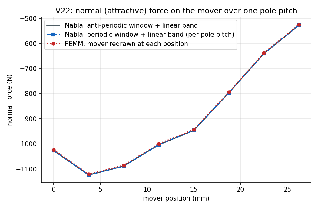
profile | min=-1124, max=-527, rms=916.9 N | min=-1121, max=-524.2, rms=913.8 N | L2 +0.336 %, max +0.323 % | L2 2.000 %, max 2.000 % | PASS |
thrust_periodic_N |
profile | min=-249.3, max=125.4, rms=165.3 N | min=-249.8, max=126, rms=165.2 N | L2 +0.269 %, max +0.307 % | L2 0.500 %, max 0.500 % | PASS |
normal_force_periodic_N |
profile | min=-1124, max=-461.3, rms=877.9 N | min=-1124, max=-461.9, rms=878 N | L2 +0.041 %, max +0.066 % | L2 0.500 %, max 0.500 % | PASS |
thrust_band_probe_N |
profile | min=-250.1, max=125.4, rms=170 N | min=-249.4, max=124.9, rms=169.6 N | L2 +0.245 %, max +0.255 % | L2 1.000 %, max 1.000 % | PASS |
normal_force_band_probe_N |
profile | min=-1124, max=-525.6, rms=916.2 N | min=-1120, max=-523.9, rms=913.7 N | L2 +0.283 %, max +0.312 % | L2 1.000 %, max 1.000 % | PASS |
thrust_vs_femm_max_rel |
abs | 0.00486514 - | 0 - | 0.004865 | 0.02 | PASS |
normal_force_vs_femm_max_rel |
abs | 0.00323269 - | 0 - | 0.003233 | 0.02 | PASS |
periodic_vs_antiperiodic_thrust_max_rel |
abs | 0.00307427 - | 0 - | 0.003074 | 0.005 | PASS |
periodic_vs_antiperiodic_normal_max_rel |
abs | 0.000662063 - | 0 - | 0.0006621 | 0.005 | PASS |
band_vs_conforming_thrust_max_rel |
abs | 0.00254797 - | 0 - | 0.002548 | 0.01 | PASS |
band_vs_conforming_normal_max_rel |
abs | 0.00311665 - | 0 - | 0.003117 | 0.01 | PASS |
band_force_vs_probe_thrust_max_rel |
report | 0.00395324 - | - - | - | - | REPORT |
band_force_vs_probe_normal_max_rel |
report | 0.00127174 - | - - | - | - | REPORT |
conforming_vs_femm_thrust_max_rel |
report | 0.00330305 - | - - | - | - | REPORT |
conforming_vs_femm_normal_max_rel |
report | 0.00054354 - | - - | - | - | REPORT |
gap_By_vs_femm_l2 |
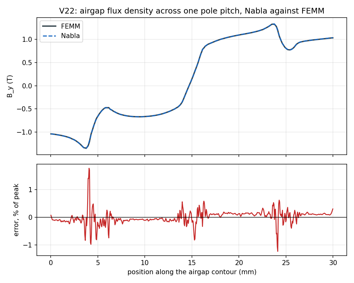
report | 0.00365421 - | - - | - | - | REPORT |
gap_By_conforming_vs_femm_l2 |
report | 0.00322282 - | - - | - | - | REPORT |
band_gap_deficit_frac |
report | 0.00129462 - | - - | - | - | REPORT |
thrust_cogging_share |
report | 0.162586 - | - - | - | - | REPORT |
thrust_fundamental_N |
report | 160.092 N | - N | - | - | REPORT |
band_wrap_thrust_N |
report | -125.532 N | - N | - | - | REPORT |
mesh_nodes_band_ap |
report | 38746 - | - - | - | - | REPORT |
mesh_nodes_band_p |
report | 76964 - | - - | - | - | REPORT |
mesh_nodes_conforming |
report | 38451 - | - - | - | - | REPORT |
mesh_noise_thrust_max_rel |
report | 0.00301804 - | - - | - | - | REPORT |
mesh_noise_normal_max_rel |
report | 0.000742146 - | - - | - | - | REPORT |
mesh_nodes_band_ap_alt |
report | 50837 - | - - | - | - | REPORT |
gap_By_band_T |
report | (series) | - | - | - | REPORT |
gap_By_conforming_T |
report | (series) | - | - | - | REPORT |
normal_force_antiperiodic_N |
report | (series) | - | - | - | REPORT |
normal_force_conforming_N |
report | (series) | - | - | - | REPORT |
normal_force_mesh_control_N |
report | (series) | - | - | - | REPORT |
thrust_antiperiodic_N |
report | (series) | - | - | - | REPORT |
thrust_conforming_N |
report | (series) | - | - | - | REPORT |
thrust_mesh_control_N |
report | (series) | - | - | - | REPORT |
band_force_vs_probe_thrust_max_rel: Nabla's own linear-band force pair against this case's hand-integrated stress contour, on ONE solution. Reported rather than judged: it compares two instruments and so says nothing about the band, the window or the code - but it is the number that says whether the instrument this case built is the one the product reports. The two contours are separated by nothing but current-free air, so they integrate the same fluxband_force_vs_probe_normal_max_rel: The same for the normal forceconforming_vs_femm_thrust_max_rel: Nabla WITHOUT a band against FEMM: the same conforming geometry, the same instrument, two codes. Reported rather than judged because the plan's 2 % row is the banded one; this is the number that separates a cross-code disagreement into the part the band owns and the part the codes owe each otherconforming_vs_femm_normal_max_rel: The same for the normal forcegap_By_vs_femm_l2: Relative L2 of the airgap flux density along the shared contour, banded Nabla against FEMM, with the mover half a pole pitch on. Reported rather than judged: the plan's tolerances are on the force, and a pointwise field comparison across two meshers on a semi-closed slot opening would be measuring the meshesgap_By_conforming_vs_femm_l2: The same field comparison for the conforming Nabla model, which is geometrically the same drawing FEMM was givenband_gap_deficit_frac: The unmeshed strip between the two band lines as a fraction of the magnetic circuit it is missing from (2.01 mm of airgap plus 6 mm of magnet at mu_r = 1.05). Arithmetic on the geometry, not a measurement: it is the systematic bias every band-against-something row is read through, and it is why the FEMM and conforming rows are expected to sit slightly low rather than symmetrically about zerothrust_cogging_share: Amplitude of the slot-pitch (third) harmonic of the thrust as a fraction of its peak. Published because it is what decides whether the tolerances in this case are measuring the solver or the instrument: with fully open slots this machine's detent force was as large as its useful thrust, which is the regime V05's F2 and V14's cogging rows say not to judge. The slots are semi-closed for that reasonthrust_fundamental_N: Amplitude of the fundamental (one period per pole pitch) of the thrust - the current-driven force the machine is for, set beside the cogging shareband_wrap_thrust_N: Thrust at record 8, the mover one whole pole pitch on: the anti-periodic band's constraint has wrapped all the way round with its sign flip, and the machine is its own anti-image (magnets reversed, currents unchanged). Published as a number because there is no closed form for it; it is JUDGED, against the periodic window, inside thrust_periodic_Nmesh_nodes_band_ap: Mesh nodes of the anti-periodic banded modelmesh_nodes_band_p: Mesh nodes of the periodic banded model, whose window is twice as widemesh_nodes_conforming: Mesh nodes of one conforming model - the same window as band_ap without the two band lines and the strip between themmesh_noise_thrust_max_rel: The case's own mesh noise on a thrust row: band_ap solved again with every mesh edge scaled by 0.87, so no division count and no interior element is shared, at the same nine displacements of the same band. Reported rather than judged - there is no tolerance on a mesh - and it is the number the periodic-against-anti-periodic row must be read through, because those two windows are different lengths and cannot carry the same node spacing eithermesh_noise_normal_max_rel: The same for the normal forcemesh_nodes_band_ap_alt: Mesh nodes of the mesh-noise control modelgap_By_band_T: extracted but not frozen in expected.json - reported onlygap_By_conforming_T: extracted but not frozen in expected.json - reported onlynormal_force_antiperiodic_N: extracted but not frozen in expected.json - reported onlynormal_force_conforming_N: extracted but not frozen in expected.json - reported onlynormal_force_mesh_control_N: extracted but not frozen in expected.json - reported onlythrust_antiperiodic_N: extracted but not frozen in expected.json - reported onlythrust_conforming_N: extracted but not frozen in expected.json - reported onlythrust_mesh_control_N: extracted but not frozen in expected.json - reported only
5. Discussion
The case's own claim is comfortable. The plan asks for the force pair against FEMM at 2 %; Nabla's linear-band force path lands at +0.49 % on thrust and +0.32 % on the normal force, worst position, across a sweep in which the thrust changes sign and the normal force changes by a factor of two. The airgap field along the shared contour agrees to +0.37 % in relative L2.
The band is not where the cross-code difference lives. The conforming Nabla models - the same drawing FEMM was given, no band anywhere - differ from FEMM by +0.33 % on thrust, which is most of the +0.49 % the banded model shows. What the band adds on top is the band-against-conforming row: +0.25 % and +0.31 %, both inside the 1 % V14 fixed for the same comparison on the rotary band. Splitting the cross-code number that way is the reason the eight conforming models exist; without them, 0.6 % against FEMM would be an unattributed 0.6 %.
The periodic-against-anti-periodic row passes, and getting it there took a convergence study rather than an argument. The plan fixes 0.5 % and the measurement is +0.31 % on thrust (+0.07 % on the normal force). The case's first draft failed this row at 1.33 %, and the two explanations it offered were both wrong; case V22 finding F3 is the full account, and the short version is worth keeping here because it is the only row of this case whose value depended on a decision about the mesh:
- It was not the wrap. The deviation is spread across the sweep and is smallest at record 8 - the mover one whole pole pitch on, where the anti-periodic band has carried its constraint all the way round with the sign flip that makes it anti-periodic, and the periodic band on a window twice as wide has not wrapped at all. A wrap defect would show up there and nowhere else; this is the opposite pattern.
- It was not the two windows being incommensurable. The first draft rounded
every division count up to a prime (a workaround for the Triangle crash below)
and blamed the row on the resulting different node spacing. With that
workaround removed the two windows became commensurate -
band_pat exactly 2×band_ap's node count - and the row got worse, 1.33 % to 1.66 %. Triangle's Steiner insertion is not a function of the boundary counts, so the two interiors are independent either way. - It was the mesh being too coarse, and it converges. Refining
band_apandband_puniformly: 1.655 % at the first draft's mesh, 0.307 % at half the edge length, 0.356 % at 0.4. The row falls by 5× and then sits on a floor of about 0.3 %.
So the mesh is refined by 2× (build.NABLA_MESH_REFINE) and the tolerance is
not moved: it is still the 0.5 % the validation plan fixed before this case
was ever pointed at Nabla. The honest reading is that the linear band's periodic
and anti-periodic forms agree to about 0.3 %, and that the case cannot say what
that remaining 0.3 % is - its own mesh-noise control (band_ap_alt, the same
band and the same window on an independently scaled mesh) reads
+0.30 % on thrust and
+0.07 % on the normal force, which is the same
number as the row itself. The two windows' residual difference and the cost of
any two meshes of this machine are indistinguishable here, and both are inside
the tolerance.
That control is also what the first draft got wrong. It read 0.81 % of mesh noise beside a 1.33 % row and concluded the tolerance was below the instrument's resolution. Both numbers were properties of the same coarse mesh, and refining it moved them together - 1.33 % to 0.31 %, 0.81 % to 0.30 %. A noise floor measured at one mesh bounds that mesh, not the case.
Two findings the case made in the product, both since fixed.
F1 - a linear motion profile's speed was metres per second, whatever the
model's length unit. UnifiedFormat.saveMotionMFS sent the profile speed out
unscaled while multiplying the same motion's initialPosition by
lengthUnitScaling, and Results.interpolateLinearOffset, the solver's
applyBC and MotionChecks.strokeInModelUnits all divided the speed back - three
readers agreeing with each other and with nothing else in the model. On a
millimetre model a speed of 30 therefore meant 30 m/s. The symptom was not an
error: 30 mm/s written as 30 advanced the mover by exactly one pole pitch per
step, so the sweep alternated between two positions - each a perfectly converged,
perfectly plausible solution - instead of walking. Fixed: a linear profile
speed is now model length units per time unit, like the initial position beside
it and like the circular peer's degrees per second. The wire is unchanged, so
this case's .mfs and its results are byte-identical across the fix; a model
written against the old behaviour needs its linear speeds multiplied by 1000 on a
millimetre model.
F2 - a Triangle crash looked like a missing file. Nabla runs Triangle with
-X (no exact arithmetic), and every boundary of this machine is axis-aligned,
so two parallel lines whose division counts share a factor put nodes at the same
abscissa and four such nodes are an exactly degenerate incircle test. The
divide-and-conquer Delaunay does not warn: the process died with 0xC00000FD, a
stack overflow, and Nabla reported "Node or edge file not found" - because the
exit status was logged and dropped, and the mesh files Triangle leaves under a
fixed name may still be the previous mesh. Fixed: Mesher.GenerateMesh now
names a non-zero status, retries the same input with -i (incremental Delaunay,
which meshes it), and refuses a mesh that was never written. The prime division
counts the first draft used to route around the crash are gone with it.
The unmeshed band strip is 0.13 % of the magnetic circuit and is the one systematic bias in the band's favour or against it. It is why the band rows are expected to sit slightly low rather than symmetrically about zero, and at this size it is well under every row it could move.
6. Limitations
- One machine, one operating point, one excitation. The currents are DC and fixed for the whole sweep. Nothing here tests a linear machine driven by a circuit, by eddy currents, or at a synchronous operating point.
- Linear iron. No saturation anywhere, in either code. V02 is the BH case.
- P1, planar, static physics. The linear band is not tested at
polyOrder = 2here, nor with eddy currents, nor with more than one motion zone. The linear peer of V14's mover/mover interface is untested. - The force pair comes off a single mid-band contour. Unlike the rotary
torque, which
Results.bandGapLayerTorqueaverages over the whole airgap layer (Arkkio) precisely because a single circle reads the mesh (case V05 finding F2), the linear force is one contour. This case's thrust is dominated by a current-driven fundamental, so it does not expose that; a detent-force sweep of a linear machine, where the net is orders of magnitude below the integrand, would, and it is not attempted here. - The 0.5 % row needs this mesh. It passes at
NABLA_MESH_REFINE = 0.5and fails at 1.0 (see §5), so the claim this case supports is that the periodic and anti-periodic linear bands agree to about 0.3 % when both are resolved. The floor is the two windows' band rings, not either mesh, and this case does not establish how that floor scales with ring length or airgap. - The refinement is bounded above by the solver. At roughly 180 000 nodes
solver.exedies with a stack overflow of its own (0xC00000FD), which is why the study stops at 0.4 and the case runs at 0.5 (77 000 nodes on the widest model). That crash is unexplained and is not this case's subject. - The FEMM comparison is across two mesh densities now.
geometry.json'smesh_edge_mmstill describes the mesh FEMM's frozen reference was computed on;NABLA_MESH_REFINErefines Nabla only. Both codes are converged well inside the 2 % the row is judged at, but the two meshes are no longer the same drawing refined the same way. - FEMM is a code, not a measurement. Two 2D FEM codes agreeing to 0.6 % is evidence that neither has a gross error in this configuration; it is not evidence about reality. There is no measured linear machine in this chapter.
7. Reproduce
cd validation
python -m harness.run_case V22
Requires a built triangle.exe (Nabla does not distribute it)
and a solver binary. No gated feature is used, but since the mesh was refined for
§5 every model is over the free tier's 25 000-node cap (38 000 on the
one-pole-pitch window, 77 000 on the periodic one), so the case needs a licence
that lifts it. Artifacts, including all eleven models, land in
cases/V22_linear_machine/artifacts/.
To regenerate the third-party reference (needs pyfemm and FEMM 4.2 on Windows):
cd validation/cases/V22_linear_machine/reference
python femm_linear.py
8. Changelog of the frozen reference
No entry: the reference values and tolerances are as first frozen.